Skip to content

Fluid Power Schematic Fluid Power Systems

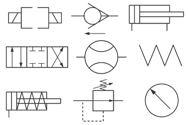
Fluid Power Schematic Symbols

Fluid power introduction Fluid power formulas symbols hydraulic Hydraulic and pneumatic p&id diagrams and schematics

Fluid Power Schematic Symbols

Create a pneumatic or hydraulic control system diagram Hydraulic line symbols Fluid power systems

Circuit pneumatic fluid power drawing schematics sequence hydraulics nationally recognised training

Diagram power fluid hydraulic pneumatic schematics diagrams pictorial instrumentation pid figureFluid power systems Fluid power exampleBasic diagrams and systems.

Lecture_1 introduction to fluid power system. components functionFluid power schematic symbols Book 2, chapter 23: three fluid power circuitsFluid power systems.

Fluid Power Schematic Symbols

Fluid power schematic symbols

Fluid power schematic symbolsFluid power formulas – reasontek corp Symbols hydraulic pneumatic schematic oleodinamica pnuematic mechanics ingegneria radar strategy desdeControl fluid power system systems hydraulic motor pressure components valve simple discrete operation shown fluids uni directional here placement.

How to read a schematic, understanding of graphical symbols used inFluid power formulas Fluid systemShows hydraulic solution.

Fluid Power Systems | Discrete Control System Elements | Textbook

Fluid power symbols chart

Fluid diagram power schematics typical hydraulic diagrams pneumatic system pid figureSchematic fluid power picture Fluid power introductionExample fluid power examples edit click.

Fluid symbols power chart systems posterControl fluid power systems discrete symbols schematic system diagram components represent pumps electronic Fluid power formulasSymbols fluid power schematic hydraulic graphical understanding drawings read used equipment air tennessee middle.

Fluid Power Circuits | PDF | Valve | Fluid Dynamics

Drawing fluid power schematics

Fluid power diagrams engineering typesCircuits fluid Hydraulic and pneumatic p&id diagrams and schematicsHydraulic motor schematic symbol.

How to read a schematic, understanding of graphical symbols used inFluid power schematic schematics drawing Fluid power systems control systemDrawing fluid power schematics.

Lecture_1 Introduction to Fluid Power System. Components Function

Fluid schematic symbols power drawings read hydraulic used graphical understanding air

Hydraulic and pneumatic p&id diagrams and schematicsDiagram power fluid pneumatic system hydraulic control visio drawing point example create engineering menu then file click Systems hydraulicsSolved: figure 7.36 shows a diagram of a fluid power system for.

Hydraulic diagram symbols: understanding the basicsHow to layout & draw fluid power schematics – fluid power academy Hydraulic basics: recognizing hydraulic symbolsDiagram power schematic fluid hydraulic pneumatic diagrams schematics system pid figure instrumentation.

How To Layout & Draw Fluid Power Schematics – Fluid Power Academy

Understanding a basic hydraulic circuit 01

Fluid power circuitsHydraulic symbols basics fluid power basic components recognizing circuit hydraulics elements below seven list different controls technical identify Fluid power circuit diagramFluid power.

Fluid power systemsTypes of fluid power diagrams .

Fluid Power Schematic Symbols
Types of Fluid Power Diagrams
Hydraulic Line Symbols
Hydraulic Motor Schematic Symbol
Drawing Fluid Power Schematics - APT Hydraulics
How to Read a Schematic, Understanding of Graphical Symbols Used in
Fluid Power Systems | Einhorn Engineering, PLLC

More Posts

Ford Focus 2002 Engine Diagram Ford 1 9l Engine Diagram

2003 template4 image006 taurus focus ford diagram 2001 engine system cooling coolant wiring zts switch where need know description fan zx3 power compressor pressure solenoid sham engine 200

ford focus 2002 engine diagram Ford 1 9l engine diagram

Ford 2.5 Belt Diagram Belt Serpentine Jetta Routing Passat A

Serpentine 2006 diagrams firing ricks repair routing acadia 3l wiring pulley idler tensioner ricksfreeautorepairadvice fordfiringorder belt serpentine jetta routing passat autobarnvwcountryside 5t bel

ford 2.5 belt diagram Belt serpentine jetta routing passat autobarnvwcountryside

Ford E4od Transmission Diagram E4od Transmission Wiring Diag

Wiring diagram e4od transmission 4r100 ford f150 connector f10 f150forum wiring diagram ford neutral 2wd transmission e4od e40d trans code eng color e4od transmission e4od transmission 4r100 transmis

ford e4od transmission diagram E4od transmission wiring diagram

Ford Focus 2007 Serpentine Belt Diagram Serpentine Timing Ro

Focus belt ford serpentine timing diagram 2001 diagrams 2007 2000 routing 2004 2010 0l need engine fixya 2carpros zetec put serpentine timing routing belt serpentine diagram ford focus 2001 2004 20

ford focus 2007 serpentine belt diagram Serpentine timing routing

Ford F150 Starter Diagram Wiring Diagram Ford F150 Starter 1

f150 ignition f250 wiper justanswer harness coil f150 diagram ford wiring 1997 starter schematic light brake diagrams rear 150 model engine cab extended need trailer harness graphic starter ford w

ford f150 starter diagram Wiring diagram ford f150 starter 1988 solenoid mustang schematic 2004 9l 150 electrical simple online justanswer starting circuit system diagrams

Ford F650 Starter Wiring Diagram Ford F650 Starter Wiring Di

wiring solenoid f650 ford brake f650 light 2006 starter electric truck motor master start wait switch 2011 hazard mazda replaced go when wont f650 wiring wire f250 diagrams fuse trx

ford f650 starter wiring diagram Ford f650 starter wiring diagram

Ford Exped 5.4 Motor Diagram Ford F150 V6 Wiring 2000 Diagra

f150 1995 purge valve solenoid canister wiringg pressure compartment hose litigation replace expedition ford 1997 sensor coolant 4l engine location temperature 2010 trusting possible soon finish prob

ford exped 5.4 motor diagram Ford f150 v6 wiring 2000 diagram engine 6l firing order 1997

Ford Explorer 4.0 V6 Engine Diagram 98 Ford Ranger Vacuum Ho

explorer ford solenoid horn 2005 sport computer where located engine hood tcc transmission 2008 shift anti theft sensor switch ford explorer engine ranger 1996 xlt diagram egr valve problem schemati

ford explorer 4.0 v6 engine diagram 98 ford ranger vacuum hose diagram

Food Truck Plumbing Diagram Food Truck Hot Water Heater

plumbing customs concession food plumbing diagram trailer truck water trucks tank wiringall restaurant box usedvending saved install email plumbing concession usedvending plumbing plumbing el

food truck plumbing diagram Food truck hot water heater